SFP 100G LR4 10km QSFP28+
Price: Rs 24336.28
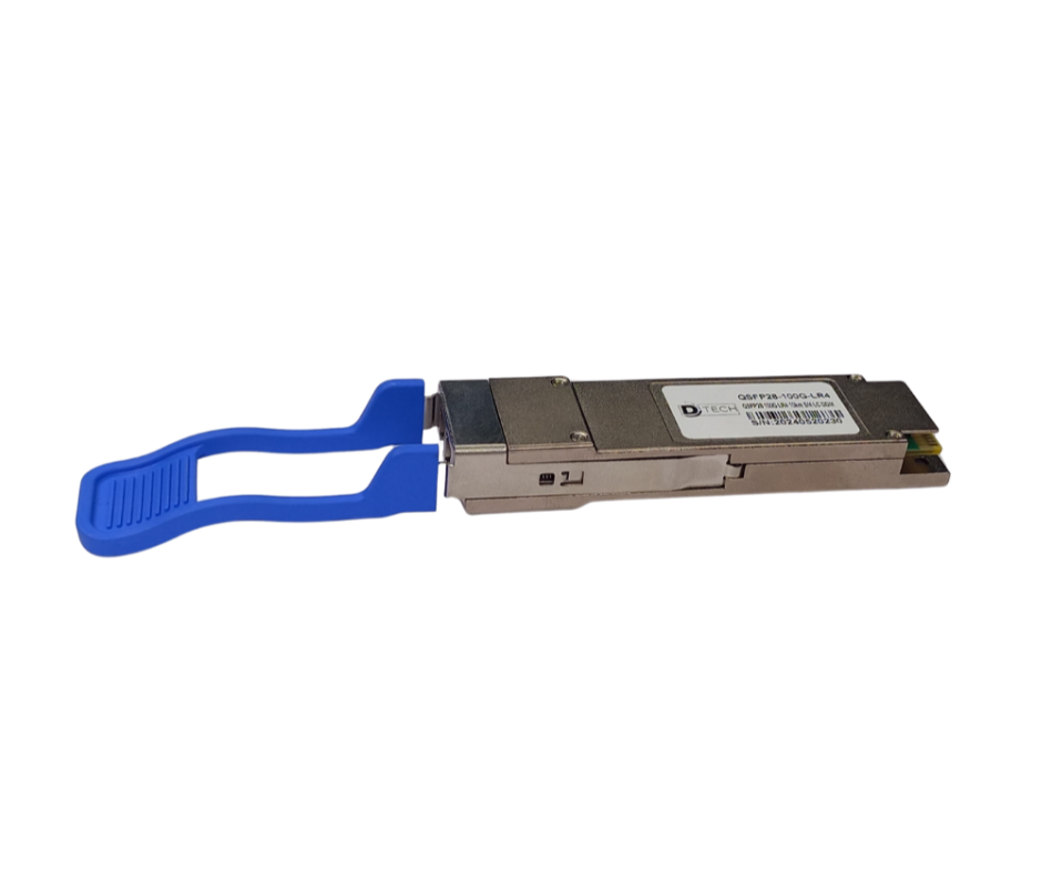
100G LR4 10km QSFP28+
Product Overview:
HTF’100G QSFP28 LR4 optical Transceiver integrates receiver and transmitter path on one module. On the transmit side, four lanes of serial data streams are recovered, retimed, and passed to four laser drivers. The laser drivers control a 4-distributed Feedback Laser (DFB) with center wavelength of 1296 nm, 1300 nm, 1305 nm, and 1309 nm. The optical signals are multiplexed to a single-mode fiber through an industry-standard LC connector. In the receiving side, the four lanes of optical data streams are opticallydemultiplexed by the integrated optical de-multiplexer. Each data stream is recovered by a PINphoto-detectorand trans-impedance amplifier, retimed. This module features a hot-pluggable electrical interface, low-power consumption, and MDIO management interface. The product is designed with form factor, optical/electrical connection and digital diagnostic interface according to the QSFP28 Multi-Source Agreement (MSA) and is compliant to IEEE 802.3bm.
Features:
- Compliant with 100GBASE-LR4
- Support line rates from 103.125 Gb/s to 111.81 Gb/s
- Integrated LAN WDM TOSA / ROSA for up to 10 km reach over SMF
- CAUI (10x10G) Electrical Interface and 4-lane 25.78 GB/s optical interface
- Duplex LC optical receptacle
- Support a Diagnostic Monitoring interface
- No external reference clock
- RoHS-6-compliant and lead-free
- Compliant with QSFP28 MSA with LC connector
- Single +3.3V power supply
- Maximum power consumption: 3.5W
- All-metal housing for superior EMI performance
- Case operating temperature: Commercial: 0 ~ +70°C
Applications:
- Data Center
- Local Area Network (LAN)
- Ethernet switches and router applications
Recommended Operating Conditions and Power Supply Requirements:
| Parameter | Symbol | Min | Typical | Max | Unit | Notes |
|---|---|---|---|---|---|---|
| Operating Case Temperature | TOP | 0 | 70 | °C | Commercial | |
| Power Supply Voltage | VCC | 3.135 | 3.3 | 3.465 | V | |
| Data Rate | 100 | Gb/s | ||||
| Control Input Voltage is high. | 2 | VCC | ||||
| Control Input Voltage is low. | 0 | 0.8 | V | |||
| Link Distance (SMF) | D | 10 | km | 9/125um |
. Electrical Characteristics:
| Parameter | Symbol | Min | Typ. | Max | Unit | Notes |
|---|---|---|---|---|---|---|
| Power Consumption | p | 3.5 | W | |||
| Supply Current | Icc | 1060 | mA | |||
| Transmitter Single-ended Input Voltage Tolerance | Vcc | -0.3 | 4.0 | V | ||
| Differential Input Voltage Swing | Vin,pp | 180 | 1000 | mVpp | ||
| Differential Input Impedance | Zin | 90 | 100 | 110 | Ohm | 1 |
| Transmit Disable Assert Time | 10 | us | ||||
| Transmit Disable Voltage | Vdis | Vcc-1.3 | Vcc | V | ||
| Transmit Enable Voltage | Ven | Vee | Vee+0.8 | V | 2 | |
| Receiver Differential Output Voltage Swing | Vout,pp | 300 | 850 | mVpp | ||
| Differential Output Impedance | Zout | 90 | 100 | 110 | Ohm | 3 |
| Data output rise/fall time | Tr/Tf | 28 | ps | 4 | ||
| LOS Assert Voltage | VlosH | Vcc-1.3 | Vcc | V | 5 | |
| LOS De-assert Voltage | VlosL | Vee | Vee+0.8 | V | 5 |
Optical Characteristics:
| Parameter | Symbol | Min | Typical | Max | Unit | Notes |
|---|---|---|---|---|---|---|
| Transmitter Lane wavelength (range) | ||||||
| L0 | 1294.53 | 1295.56 | 1296.59 | nm | ||
| L1 | 1299.02 | 1300.05 | 1301.09 | nm | ||
| L2 | 1303.54 | 1304.58 | 1305.63 | nm | ||
| L3 | 1308.09 | 1309.14 | 1310.09 | nm | ||
| Signaling rate, each lane | 25.78125 | GBd | ||||
| Side-mode suppression ratio | SMSR | 30 | ||||
| Total launch power | 10.5 | dBm | ||||
| Average launch power, each lane | Pavg | -4.3 | 4.5 | dBm | ||
| Extinction Ratio | ER | 4 | dB | |||
| Transmitter and Dispersion Penalty, each lane | TDP | 2.2 | dB | |||
| OMA minus TDP, each lane | OMA-TDP | -2.3 | dBm | |||
| Average launch power of OFF transmitter, each lane | -30 | dBm | ||||
| Transmitter reflectance | -12 | dB | ||||
| Transmitter eye mask: {X1, X2, X3, Y1, Y2, Y3} | {0.25, 0.4, 0.45, 0.25, 0.28, 0.4} | |||||
| Receiver Signaling rate, each lane | 25.78125 | GBd | ||||
| Receiver Sensitivity per lane | Rsen | -10.6 | dBm | 1 | ||
| Input Saturation Power (overload) | Psat | 4.5 | dBm | |||
| LOS Assert | LOSA | -30 | dBm | |||
| LOS De-assert | LOSD | -12 | ||||
| Receiver reflectance | Rr | -26 | ||||
| LOS Hysteresis | 0.5 | 4 | dB |
Digital Diagnostic Functions:
| Parameter | Symbol | Min | Max | Unit | Notes |
|---|---|---|---|---|---|
| Temperature monitor: absolute error | DMI_Temp | -3 | 3 | degC | Over operating temperature |
| Supply voltage monitor absolute error | DMI_VCC | -0.15 | 0.15 | V | Full operating range |
| RX power monitor: absolute error | DMI_RX | -2 | 2 | dB | |
| The current monitor | DMI_bias | -10% | 10% | mA | |
| TX power monitor absolute error | DMI_TX | -2 | 2 | dB |
Here are some related SFP links below:
SFP 100G SR4 850nm 100Mtr QSFP28+:
SFP 100G BIDI QSFP28 LR1-10Km:
SFP 100G BIDI QSFP28 LR1-20Km: